

| Caractéristiques |
| Synoptique |
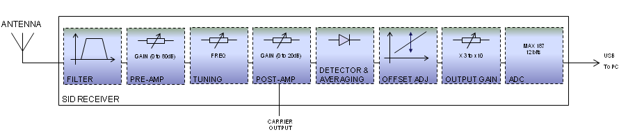
The basic principle of the SID receiver is to measure the amplitude of a VLF station and to convert it to digital data.
The signal from the antenna (usually a loop antenna) is filtered out to limit the signals to the frequencies of interest in the VLF and lower-LF frequency range.
The RF pre-amplifier section is built around one non-inverting amplifier with a gain of 21 and two inverting amplifier stages with gains adjustable between 0 and 25.
The signal is then filtered in the tuning section. The MAX275 is a continuous-time 4th-order active filter. The MAC275 is configured as a bandpass filter; center frequency, gain and Q are adjusted by resistors.
The following section is the RF post amplifier. It has a gain adjustable between 0 and 10. A buffer provides an optional carrier output with a 50Ω impedance.
Then, a full-wave rectifier and peak detector is used as a linear detector converting the RMS value of the VLF station to a DC voltage level. This level is averaged (default time constant around 1 minute) to produce a signal strength value.
DC offset can be applied to the signal strength value, before further amplification in the output amplifier section (selectable gains of x3.25, x4 and x10).
Finally, the analog to digital conversion is performed by the 12-bits ADC MAX187.
The interface between the MAX187 and the computer is done though an USB port.
Le design du récepteur a été inspiré du récepteur du Stanford Solar Center. Voir Stanford SID monitor.
Vous trouverez ci-dessous les schémas du récepteur SID, ainsi que la liste des composants :
 Schéma du récepteur SID v1.1 Schéma du récepteur SID v1.1 | (application/pdf, 116Kb, 05 Mar 2011) | |
| Schéma de l'alimentation du récepteur | (application/pdf, 20Kb, 05 Mar 2011) | |
| Liste des Composants du récepteur | (application/pdf, 88Kb, 10 Apr 2011) | |
| Valeurs des résistances de réglage de la fréquence | (application/pdf, 45Kb, 17 Mar 2011) | |
| Manual de construction du récepteur | (application/pdf, 15609Kb, 12 Jul 2011) |
Pour visualiser ces fichiers, vous pouvez utiliser un logiciel tel que SumatraPDF (Windows) :
 ou Adobe® Reader® (Windows, Mac, Linux) :

| Circuit Imprimé |
| Réglages |
| Assemblage final |
| Protocole de Transfert de données |
Voici quelques précisions sur le protocole de tranfert de données entre le MAX187 et l'interface RS-232.
Les signaux du MAX187 sont affectés ainsi aux broches RS-232 :Le standard RS-232 définit une tension positive comme correspondant à un niveau logique zero et une tension négative comme un niveau logique 1.
Le protocole de communication est détaillé dans les documents suivants :| • Datasheet du MAX187 | |
| • Application note Maxim n°827. Cette note contient un code C à titre d'exemple. |

|
SID Monitoring Station de Lionel LOUDET est mis à disposition selon les termes de la licence Creative Commons Attribution - Pas d’Utilisation Commerciale - Partage dans les Mêmes Conditions 3.0 non transposé. |
|
| Dernière mise à jour : 20 Jul 2013 |
|
Apache/2.4.66 (Debian) |
|