

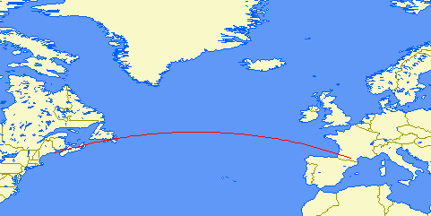
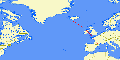
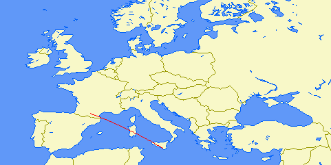
This section indicates, for each monitored transmitter, the distance and bearing from the receiving station.
The location of the subreflective point(s) of each signal path in precised. From one to three points exist depending on the transmitting station distance. They indicate where the sky wave bounces off the ionosphere.
In addition, the bandwidth setting of the receiver, expressed in Hertz, is shown. This bandwidth must be narrow enough to reject adjacent stations and wide enough to cover the modulated signal spectrum.
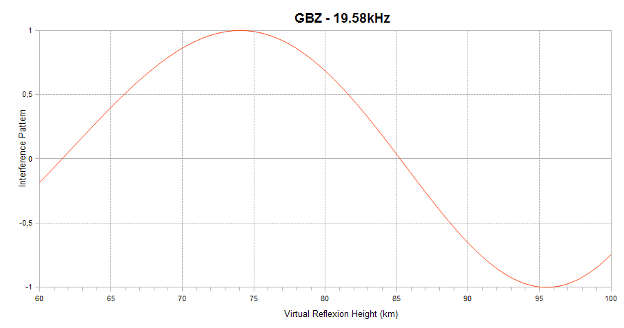
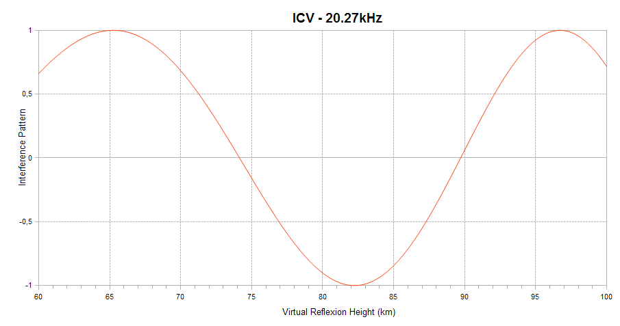
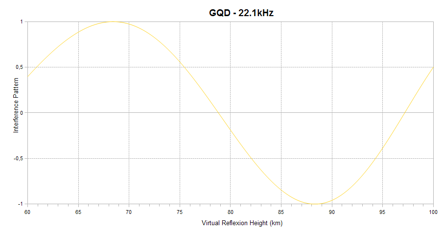
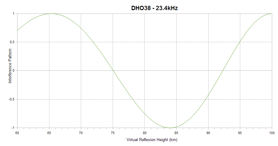
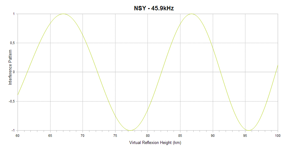
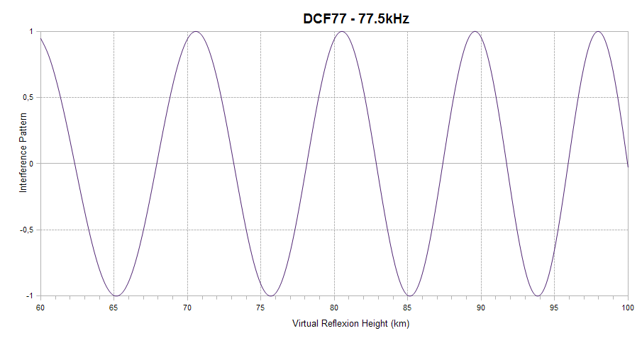
Finally, the interference pattern between the ground and sky waves is indicated. It appears as a sinusoid ranging between +1 (sky and ground waves in phase) and -1 (sky and ground waves out of phase) on the vertical axis. When in-phase, the interference is constructive and leads to a signal amplitude enhancement. When out-of-phase, the interference is destructive, and leads to signal amplitude reduction. The interference depends on the virtual reflection height of the sky wave on the D region of the ionosphere, as shown on the horizontal axis of the plot. The higher the ionisation level of the D region, the lower the reflexion height. This plot explains how solar flares affect the signal amplitude and helps understanding why a given flare can lead to a signal increase on one channel and to a signal decrease on another.
The interference pattern is defined only for short propagation paths (1D mode).
| Distance: | 1305km (1 hop) |
| Bearing: | 347° (N-S loop) |
| Sub-reflective point: | 49°12'N 000°42'W (IN99PE) |
| Receiver Bandwidth (3dB): | 100Hz |
| Linear scale |

| Distance: | 764km (1 hop) |
| Bearing: | 109° (E-W loop) |
| Sub-reflective point: | 42°16'N 005°37'E (JN22TG) |
| Receiver Bandwidth (3dB): | 110Hz |
| Linear scale |

| Distance: | 1279km (1 hop) |
| Bearing: | 348° (N-S loop) |
| Sub-reflective point: | 49°07'N 000°32'W (IN99RC) |
| Receiver Bandwidth (3dB): | 110Hz |
| Linear scale |

| Distance: | 1163km (1 hop) |
| Bearing: | 21° (N-S loop) |
| Sub-reflective point: | 48°19'N 004°10'E (JN28CH) |
| Receiver Bandwidth (3dB): | 120Hz |
| Linear scale |

| Distance: | 5300km (3 hops) |
| Bearing: | 297° (E-W loop) |
| Sub-reflective points: | 47°25'N 056°31'W (GN17RK) |
| 49°30'N 032°35'W (HN39QM) | |
| 46°34'N 009°04'W (IN56LN) | |
| Receiver Bandwidth (3dB): | 160Hz |
| Linear scale |
| Distance: | 2307km (2 hops) |
| Bearing: | 098° (E-W loop) |
| Sub-reflective points: | 39°27'N 021°17'E (KM09PK) |
| 42°31'N 008°15'E (JN42CM) | |
| Receiver Bandwidth (3dB): | 200Hz |
| Linear scale |

| Distance: | 2708km (2 hops) |
| Bearing: | 335° (N-S loop) |
| Sub-reflective points: | 59°14'N 014°00'W (IO39AF) |
| 48°55'N 002°40'W (IN88QW) | |
| Receiver Bandwidth (3dB): | 420Hz |
| Linear scale |
| Distance: | 1331km (1 hop) |
| Bearing: | 118° (E-W loop) |
| Sub-reflective points: | 40°29'N 008°11'E (JN40CL) |
| Receiver Bandwidth (3dB): | 560Hz |
| Linear scale |
| Distance: | 937km (1 hop) |
| Bearing: | 036° (N-S loop) |
| Sub-reflective points: | 46°48'N 004°56'E (JN26LT) |
| Receiver Bandwidth (3dB): | 1200Hz |
| Linear scale |


|
SID monitoring station by Lionel LOUDET is licensed under a Creative Commons Attribution-NonCommercial-ShareAlike 3.0 Unported License. |
|
| Last Update: 16 Jun 2013 |
|
Apache/2.4.68 (Debian) |
|