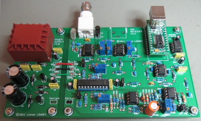
Here are the main characteristics of the SID receiver:
- single-channel receiver, tested from 15kHz to 80kHz
- included antenna preamplifier
- active order 4 bandpass filter (bandwidth of less than 200Hz for stations below 30kHz)
- measurement of the RMS amplitude
- linear output (not dB), offset setting
- 12-bits ADC
- USB interface
- power supply included
Here are some details regarding the data transfer protocol between the MAX187 and the RS-232 interface.
The MAX187 signals are connected to the following RS-232 pins:
- /CS ↔ RTS
- SCLK ↔ DTR
- DSR ↔ DOUT
The RS-232 standard defines the positive voltage levels for logic one and negative voltage level for logic zero.
Protocol is detailed in the following documents:
•  MAX187 Datasheet MAX187 Datasheet |  |
•  Maxim application note 827. This note contains a C code example. Maxim application note 827. This note contains a C code example. |  |
The overall sequence is described below:
-
Unset RTS (RTS=-5V; /CS='1') to deselect MAX187
-
Set DTR (DTR=+5V; SCLK='0')
-
Set RTS (RTS=+5V; /CS='0') to select MAX187.
This starts the conversion.
-
Wait till the conversion is done (DOUT must be '1'; DSR=-5V)
-
Clock in 12 bits. MSB are first:
- Unset DTR (DTR=-5V; SCLK='1')
- Set DTR (DTR=+5V; SCLK='0')
- Read a bit (signal DOUT, DSR)
- Add a 13th falling edge:
- Unset DTR (DTR=-5V; SCLK='1')
- Set DTR (DTR=+5V; SCLK='0')
-
Unset RTS (RTS=-5V; /CS='1') to deselect MAX187
-
Unset DTR (DTR=-5V; SCLK='1')
