Here are the main characteristics of the SID receiver:
- single-channel receiver, tested from 15kHz to 80kHz
- included antenna preamplifier
- active order 4 bandpass filter (bandwidth of less than 200Hz for stations below 30kHz)
- measurement of the RMS amplitude
- linear output (not dB), offset setting
- 12-bits ADC
- USB interface
- power supply included
A small quantity of high quality printed circuits boards for the SID receiver have been manufactured.
The author offers those boards for 30 euros plus shipping costs.
Please contact me  for availability.
The printed circuit board is out of stock. Production of another batch is not planned.
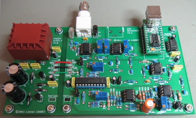
Here is a picture of the board:
Here are some details regarding the data transfer protocol between the MAX187 and the RS-232 interface.
The MAX187 signals are connected to the following RS-232 pins:
- /CS ↔ RTS
- SCLK ↔ DTR
- DSR ↔ DOUT
The RS-232 standard defines the positive voltage levels for logic one and negative voltage level for logic zero.
Protocol is detailed in the following documents:
•  MAX187 Datasheet MAX187 Datasheet |  |
•  Maxim application note 827. This note contains a C code example. Maxim application note 827. This note contains a C code example. |  |
The overall sequence is described below:
-
Unset RTS (RTS=-5V; /CS='1') to deselect MAX187
-
Set DTR (DTR=+5V; SCLK='0')
-
Set RTS (RTS=+5V; /CS='0') to select MAX187.
This starts the conversion.
-
Wait till the conversion is done (DOUT must be '1'; DSR=-5V)
-
Clock in 12 bits. MSB are first:
- Unset DTR (DTR=-5V; SCLK='1')
- Set DTR (DTR=+5V; SCLK='0')
- Read a bit (signal DOUT, DSR)
- Add a 13th falling edge:
- Unset DTR (DTR=-5V; SCLK='1')
- Set DTR (DTR=+5V; SCLK='0')
-
Unset RTS (RTS=-5V; /CS='1') to deselect MAX187
-
Unset DTR (DTR=-5V; SCLK='1')

![]() for availability.
for availability.
