No need to know how to solve Maxwell equations, but a bit of theory is necessary to follow the right track. You will found here a summary of the physical rules defining the performance of the air-core and ferrite loops used for VLF reception.
This page describes first the loop antenna theory, and then contains a study of the various parameters of a loop antenna equivalent electric circuit. A SPICE model of loop antenna is then proposed.
The section References lists additional sources of information for those willing to study more in depth the loop antennas.
For those of you who are totally adverse to maths, a synthesis at the end of each section sums up the main definitions and conclusions.
A bit of theory
Loop antenna principle
The aim of any receiving antenna is to convert an electromagnetic wave into a voltage. A magnetic loop antenna is a winding of copper wire around a frame (for air-core loops) or around ferromagnetic material (for ferrite loops).
A loop antenna is actually sensitive to the magnetic field and not the electric field (it is also called a magnetic loop). The Faraday's law of induction (or the law of electromagnetic induction) states that the induced electromotive force e(t) in a loop is directly proportional to the time rate of change of magnetic flux Φ(t) through the loop according to the relation:
 (1)
(1)where:
- he is the induced electromotive force, in V
- Φ is the magnetic flux accross the circuit, in webers (Wb ≡ V·s)
This equation is valid only for electrically short antennas with respect to the wavelength of interest, which is true for the VLF frequencies.
Let's define:
 the vector of the magnetic induction, u unit vector
 the normal vector to the frame surface, n unit vector
 where θ is the angle
  between the magnetic field lines and the frame normal.
The magnetic flux is a measure of quantity of magnetism through the antenna submitted to a given magnetic induction:
 (2)
(2)
For a sinusoidal magnetic field, uniform over the surface S, the amplitude B(t) projected on n is:
 (3)
(3) (4)
(4)where:
- B0 is the strength of the magnetic induction, in tesla (T ≡ Wb/m² ≡ V·s/ m²)
- ω is the angular frequency of the inductive magnetic field, in rad·s-1
Equation (2) gets then:
 (5)
(5) (6)
(6)
For a loop with N turns, each of them of area A, we have  , so:
, so:
 (7)
(7)
and (1) is then:
 (8)
(8)
Since  , the RMS value of the electromotive force at the output of the antenna is:
 (9)
(9)Expression of the induced voltage as a function of the electric field
The efficiency of an antenna is defined through the "effective height" parameter he according to:
 (10)
(10)where:
- Vrms is the RMS value of the voltage induced at the output of the antenna, in V
- he is the effective height, in m
- Erms is the RMS value of the electric field, in V/m
From  and since the electric field relates to the magnetic induction through
  , the effective height of a loop antenna is:
 (11)
(11)where:
- he is the effective height, in m
- N is the number of turns
- A the area of each winding, in m²
- λ is the wavelength, in m
- θ is the angle between the magnetic field lines and the frame normal
With a ferrite antenna, the magnetic induction through the antenna is increased by a factor called the relative permeability of the medium. Equation (9) becomes:
 (11 bis)
where:
- µr is the relative permeability, dimensionless quantity. µr is specific to the medium.
Quick maths will show that, taken into account the wavelengths we are interested in (15km at a frequency of 20kHz), the effective height of a loop antenna is very small compared to the signal wavelength... It is anyway possible to obtain good results with reasonable antenna designs.
Expression of the induced voltage as a function of the magnetic field
The inductive magnetic field across the loop depends on the magnetic component of the electro-magnetic wave (called H or magnetic field strength) and on the magnetic permeability of the loop core.
The inductive magnetic field B relates to the magnetic field strength H by:
 (12)
(12)where:
- B is the RMS value of the magnetic induction, in tesla (T ≡ V·s/m²)
- µ0 is the permeability of vacuum, constant of 4π10-7 H/m
- µr is the relative permeability, dimensionless quantity. µr is specific to the medium.
- H is the RMS value of the magnetic field strength, in A/m
For an air-core loop, we have µr = 1.
For a ferrite loop, the field lines are collected by the ferromagnetic properties of the core, and µr can amount to several hundreds or several thousands.
The antenna will then output a RMS voltage Vrms from a given RMS magnetic field strength Hrms value according to:
 (13)
(13)
Synthesis
The aim of any receiving antenna is to convert an electromagnetic wave into a voltage. A magnetic loop antenna is a winding of copper wire around a frame (for air-core loops) or around ferromagnetic material (for ferrite loops).
A loop antenna is actually sensitive to the magnetic field and not the electric field (it is also called a magnetic loop). It outputs a voltage proportional to that field. A particularity of this type of antenna is to provide a voltage proportional to the frequency of the signal.
The antenna performance is influenced by the number of turns and the area of each loop. For a ferrite antenna, the permeability of the core increases the output voltage.
Also, loop antennas have a toroidal reception pattern whose amplitude is maximal in the plane of the frame and zero (in theory) in the plane normal to the frame.
Equivalent electric circuit
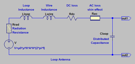
The #8801alent electric circuit of a loop antenna contains:
- an ideal voltage generator V with a value defined by equation (13)
- the radiation resistance Rrad
- the loop inductance Lloop
- the wire inductance Lwire
- the wire resistance Rdc
- the skin effect and proximity effect resistance Rac
- the distributed capacitance Cloop
Model parameters
The resistive, inductive and capacitive elements influence the performance of the antenna. We will now review their respective contribution.
The equations here below are, unless otherwize stated, valid for air-core loops and ferrite-core loops. For air-core loops, µr=1. For ferrite antennas, µr is a function of the ferrite type, dimensions and coil length.
Radiation Resistance Rrad
The radiation resistance corresponds to the "losses" in the antenna during the transformation of the electromagnetic energy into electric energy. Unlike an ohmic resistance that converts electrical energy to heat, this resistance is virtual and, consequently, does not generate thermal noise according to the Johnson-Nyquist formula. Its value is:
 (14)
(14)where:
- Rrad is the radiation resistance, in Ω
- Z0 is the impedance of free space (about 377Ω)
- µr is the relative permeability of the core
- N is the number of turns
- A is the area of each winding, in m²
- λ is the wavelength, in m
Since  , the equation (12) becomes:
 (15)
(15)Loop inductance Lloop
Air-core Square Loop
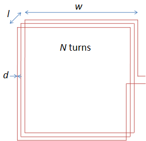
The wire winding around the frame has an inductance
Lloop that is defined by the following formula for a square frame:
 (16)
(16)where:
- Lloop is the wiring inductance, in H
- N is the number of turns
- w is the frame side length, in m
- l is the length of the winding, in m
Ferrite Loop
The wire winding around the ferrite has an inductance
Lloop that is defined by the following formula:
 (16 bis)
where:
- Lloop is the wiring inductance, in H
- µ0 is the permeability of vacuum, constant of 4π10-7 H/m
- µr is the relative permeability, dimensionless quantity. µr is specific to the medium.
- N is the number of turns
- A is the area of each winding, in m²
- l is the length of the winding, in m
Wire inductance Lwire
The wire of the antenna windings has itself an inductance. A wire of length 4
Nw has an inductance
Lwire according to:
 (17)
(17)where:
- Lwire is the wire inductance, in H.
- N is the number of turns
- w is the frame side length, in m. Total wire length is 4Nw.
- d is the wire diameter, in m.
Wire resistance Rdc
Electric wire has a resistance that is function of its length and diameter. The resistance of a wire of length 4
Nw and of diameter
d is determined by:
 (18)
(18)where:
- Rdc is the wire resistance, in Ω
- N is the number of turns
- w is the frame side length, in m. Total wire length is 4Nw.
- d is the wire diameter, in m. Wire cross section is πd²/4.
- ρ is the copper resistivity, in Ω·m. ρ=16.78nΩ·m.
This resistance is a source of thermal white noise according to the Johnson-Nyquist formula that expresses the voltage spectral density of the thermal noise by:  , in V/Hz½.
k is the Boltzmann constant (1.38·10-23 J/K), T is the absolute temperature in kelvins, and R is the resistance in ohms.
Skin effect and proximity effect resistance Rac
On top of the DC resistance described above, there is an additional high frequency resistance resulting from the fact that the current distribution is no longer homogeneous at high frequencies. The current density near the surface of the conductor is greater than that at its core, leading to the skin effect. The proximity effect results from the influence on the current distribution of close wires.
The proximity effect can be more important than the skin effect, but it is much more complex to model since it is influenced by the windings geometry. It will not be calculated here.
The skin effect resistance is:
 (19)
(19)where:
- Rac is the skin effect resistance, in Ω
- N is the number of turns
- w is the frame side length, in m. Total wire length 4Nw.
- d is the wire diameter, in m. Wire perimeter is πd.
- µ0 is the permeability of free space (4π10-7 H/m)
- f is the frequency, in Hz
- ρ is the copper resistivity, in Ω·m. ρ=16.78nΩ·m.
Distributed capacitance Cloop
The distributed capacitance approximately equals to:
 (20)
(20)where:
- Cloop is the distributed capacitance of a square frame, in F
- w is the frame side length, in m
- l is the winding length, in m
This formula is also valid for ferrite antennas, by replacing w by the diameter of the windings.
Example
In order to better evaluate the respective influence of each electric model parameter, here are some figures calculated on an example. Lets imagine a square loop, each side of
w=60 cm with
N=50 turns of enamelled copper wire #26 (diameter
d=0.405mm) winded on a length
l=1cm.
The model parameters are:
- Rrad=12.5pΩ at 10kHz, 0.125µΩ at 100kHz and 1.25mΩ at 1MHz...
This parameter can be disregarded.
- Lloop=5.77mH
- Lwire=318µH
- Rdc=15.6Ω
- Rac=2.43Ω at 10kHz, 7.67Ω at 100kHz and 24.3Ω at 1MHz.
The skin effect has a significant contribution and adds to the ohmic resistance Rdc of the wire. Moreover, this calculation does not take into account the proximity effect that is probably more important than the skin effect since the windings are very close.
- Cloop=129pF
Synthesis
The loop antenna electric model contains:
- an ideal voltage generator. The voltage is proportional to the magnetic field
- an inductance, mainly resulting from the windings inductance, but also from the inductance of the wire itself
Several parameters affect the antenna behaviour:
- a radiation resistance corresponding to the "losses" resulting from the conversion of the electromagnetic energy to electric energy. Usually, it can be disregarded.
- the wire resistance and the high frequency resistance resulting from skin and proximity effects. The high frequency resistance is closely related to the antenna geometry and is usually #8801alent to or higher than the dc resistance.
- a capacity, distributed among the windings. It can be ignored for a first approximation.
SPICE model of a loop antenna
SPICE model description
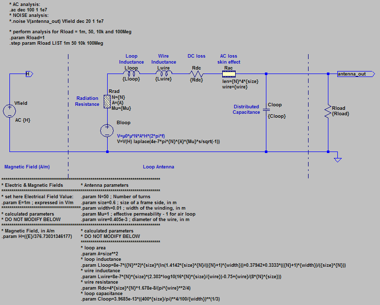
The screen capture here below describes the SPICE model.
The ideal voltage generator Bloop implements equation (13). A Laplace transform is used to model the frequency dependency of the voltage. Vfield is a voltage generator that emulates an electric field of 1mV/m.
The schematics implements the various elements of the antenna electric model and the associated equations.
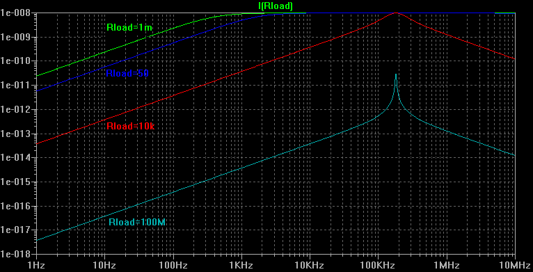
The antenna is connected to a resistive load Rload. Simulations have been done with loads of 1mΩ (close circuit), 50Ω (receiver input impedance), 10kΩ (soundcard input impedance) and 100MΩ (open circuit).
Usage in Voltage
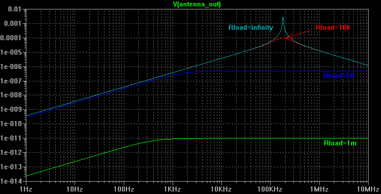
Here are the voltage values calculated at the output of the antenna:
If we have a look to the open circuit plot, we have a linear response with a rising slope of 20dB per decade corresponding to the evolution with the frequency of Bloop.
From about 100kHz, the circuit starts to resonate. The resonance frequency obeys to equation (a) below:
 (21)
(21)
Here, with L=Lloop+Lwire=6.09mH, and C=Cloop=129pF, we have f0=180kHz.
Above, the impedance of the distributed capacitance Cloop gets sufficiently low to reduce the output voltage.
By adding a resistive load, the resonance is reduced and the frequency response flattens, but the voltage levels get very low. Moreover, two poles are created:
- a high-pass filter by (Lloop+Lwire) and (Rload+Rdc+Rac).
- a low-pass filter by Cloop and Rload.
With
Rload=50Ω, by using equations (21 b) and (21 c), we have a cut-off frequency of 1.8kHz for the high-pass filter and of 25MHz for the low-pass filter.
Antenna tuning
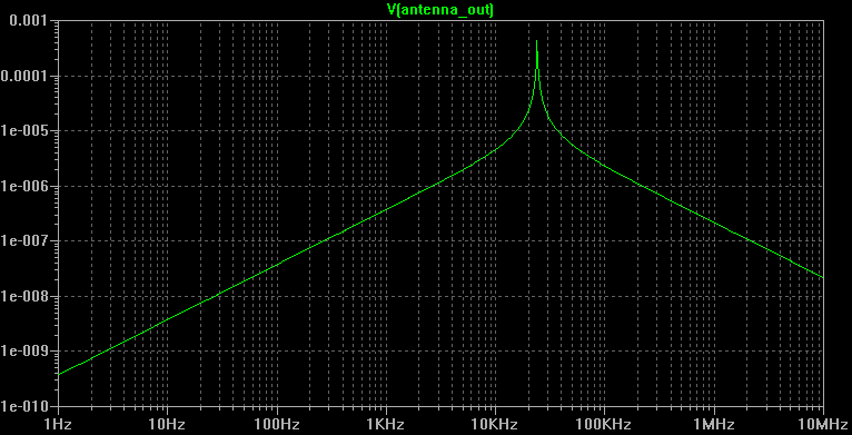
By adding a capacitor Ctune to the output of the antenna, it is possible to tune it on a given frequency. Equation (19 a) can be used to calculate its capacitance.
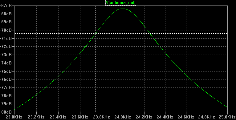
For example, if we want to tune our antenna on NAA, 24kHz, knowing the inductance (Lloop+Lwire=6.09mH), we have Ctune+Cloop=7.22nF, that is Ctune=7.09nF.
The frequency response ofg the antenna is then:
Equation (20) gives the quality factor of the antenna:
 (22)
(22)
Since
Rac=3.76Ω at 24kHz, we have
Q=47.4.
Q can also be determined by measuring the bandpass Δf at -3dB and by using the following formula:
 (23)
(23)
The measurement gives 509Hz, that is a measured Q of 47.2, in accordance with the calculated value.
A station on a close frequency (for instance DHO38 on 23.4kHz) will be strongly attenuated (by about 8dB in this case).
The real antenna quality factor will be lower since the proximity effect is not accounted for in this simulation.
Antenna current
The simulation gives the following results for the current measurements in the antenna load:
With a closed circuit, the frequency response is flat. The distributed capacitance has no detrimental effect since it is shorted.
At low frequencies, the antenna acts as a resistance. At high frequencies, this resistance gets negligible against the impedance of the inductance. This impedance (jLω) is proportional to the frequency. Since the voltage generator is also proportional to the frequency—cf. equation (13)—, the current no longer depends on the frequency.
The transition between the resistive domain (low frequencies) and the inductive domain (high frequencies), is done according to equation (19 b). The value is slightly above 400Hz in our example.
By using an operational amplifier as a current-to-voltage converter, it is possible to have an almost null impedance at the antenna output. In this specific case, the use of a transresistance of 100kΩ will give a linear reqponse of 1V/V·m-1 in the whole VLF band.
By using a non-null impedance, the antenna linearity is reduced, and has finally a resonant behaviour such as the one observed with the voltage measurements.
Synthesis
The SPICE model has shown two ideal methods for using a loop antenna:
- if one is interested in a single frequency, it is possible to tune the antenna by adding a capacitor. The antenna must then be connected to an high impedance in order to maximize the quality factor.
- if the antenna is intended to be used over a wide band, it it necessary to connect it to a short impedance and to work with its current. An operational amplifier can be used as a current-to-voltage converter. The linearity is then only limited in the low frequencies by the antenna resistance.
References
You can find additional details in the following documents:
| • The ARRL Antenna Book |  |
| • The ARRL Handbook for Radio Communications |  |
| • The website www.vlf.it is an excellent source of explanations and practical antenna designs. |  |
| • The Art of Electronics. Horowitz and Hill. The reference for electronics design! |  |
 (1)
(1) the vector of the magnetic induction, u unit vector
 the normal vector to the frame surface, n unit vector
 where θ is the angle
  between the magnetic field lines and the frame normal.
 (2)
(2) (3)
(3) (4)
(4) (5)
(5) (6)
(6) , so:
, so:
 (7)
(7) (8)
(8) , the RMS value of the electromotive force at the output of the antenna is:
 (9)
(9) (10)
(10) and since the electric field relates to the magnetic induction through
  , the effective height of a loop antenna is:
 (11)
(11) (11 bis)
 (12)
(12) (13)
(13)
 (14)
(14) , the equation (12) becomes:
 (15)
(15) (16)
(16) (16 bis)
 (17)
(17) (18)
(18) , in V/Hz½.
 (19)
(19) (20)
(20)
 (21)
(21)
 (22)
(22) (23)
(23)