The basic questions when building an antenna are which size and how many turns. As usual, "the bigger, the better" is a mis-conception and the Laws of Nature are not that simple.
As explained in the antenna theory page, bigger antennas and more turns means increased signal level at the output of the antenna. But this also means increased noise.
This page should help you in finding the optimal antenna characteristics for your application.
Firstly, it contains an analysis of the antenna noise, with a characterization of its influence with respect to the natural or man-made radio noise expected at VLF.
Then, the section Signal-to-Noise ratio is a synthesis of calculation of SNR for various antenna sizes and frequencies of interest.
 (Johnson-Nyquist formula).
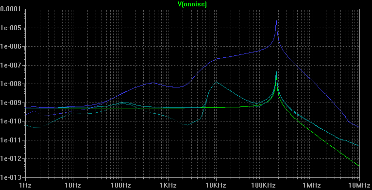
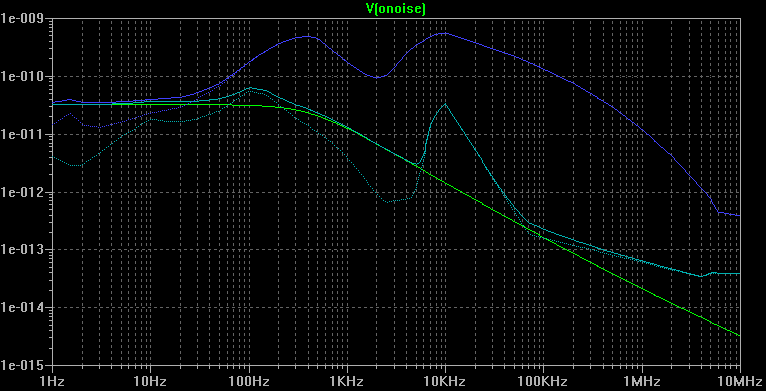
The current plots show the current noise spectral density, in A/Hz½. Those values are obtained by adding at the output of the antenna an ideal operational amplifier acting as a current-to-voltage converter with a noiseless transresistance of 1Ω. The noise voltage spectral density calculated by SPICE at the output of the converter reflect the current noise spectral density at the shorted outputs of the antenna.
The green line corresponds to the noise of the antenna only.
The blue solid line corresponds to the sum of the maximum expected radio noise and of the antenna noise.
The blue dotted line corresponds to the maximum expected radio noise only.
The cyan solid line corresponds to the sum of the minimum expected radio noise and of the antenna noise.
The cyan dotted line corresponds to the minimum expected radio noise only.
We see that, in both voltage and current analysis, the noise contribution of the antenna gets preponderant on the radio noise only below about 70Hz for maximum radio noise conditions, and below about 6kHz for ideal radio noise conditions.
Here are the figures obtained in various configurations:| Frequency range | Antenna only | Antenna + Min Radio Noise | Antenna + Max Radio Noise | |
|---|---|---|---|---|
| RMS Voltage | 1Hz-10MHz | 2.75µV | 4.64µV | 2.37mV |
| 10kHz-100kHz | 205nV | 878nV | 150µV | |
| RMS Current | 1Hz-10MHz | 833pA | 2.39nA | 97.0nA |
| 10kHz-100kHz | 140pA | 1.62nA | 77.6nA |
In this case, the antenna noise is not significant for VLF waves reception. This would not be the case for the reception of ULF, SLF or ELF waves.
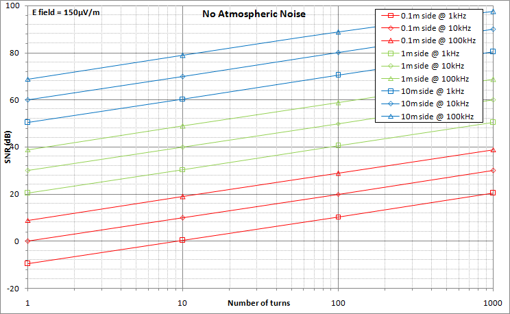
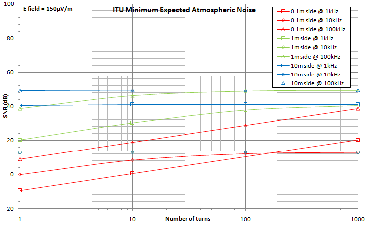
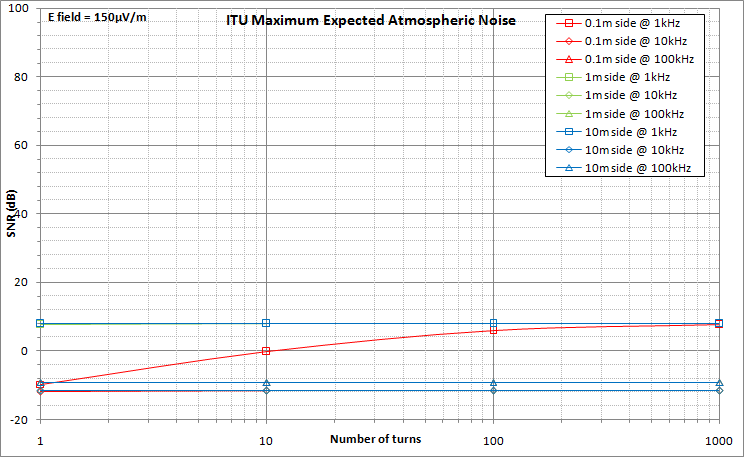
The three graphs here below show the SNR values (vertical axis, in dB) against the number of turns (horizontal axis).
Plots for antenna sizes of 0.1m by 0.1m (4" by 4"), 1m by 1m (3.3ft by 3.3ft) and 10m by 10m (33ft by 33ft) are shown.
For each antenna size, the SNR values have been determined around the frequencies of 1 kHz, 10 kHz and 100 kHz. Those three frequencies are in the linearity range of the antenna working in current. To ensure consistency, the following bandwiths have been used for the noise calculations:
The first graph assumes that there is no radio noise. This is a theoretical and ideal situation, where the noise figure is only influenced by the antenna noise. In this case, one can clearly see the influence of the antenna dimensions on the SNR ratio:
The second graph corresponds to actual conditions where the radio noise is minimal. To reach those noise levels, the best possible location must be chosen (away from man-made noises) and atmospheric noise must be low.
Even under those excellent circumstances, one can see that the antenna efficiency with respect to SNR gets non linear with respect to size or number or turns. For a "big" antenna (10m side), the number of turns has no effect at all, so a single turn antenna is sufficient, for all frequencies of interest. For an antenna with a side of 1m, the influence of the number of turns gets marginal above a few tens of turns.
The last graph corresponds to worst case conditions of radio noise. In this case, the influence of the antenna characteristics on its overall capability to extract useful signal from the overwhelming noise is quite limited.
|
SID monitoring station by Lionel LOUDET is licensed under a Creative Commons Attribution-NonCommercial-ShareAlike 3.0 Unported License. |
| Last Update: 10 Dec 2010 |
|
Apache/2.4.66 (Debian) |
|